Let \(f(z)\) be a given velocity potential such that any singularities in \(f\) occur in \(|z| > a\text{.}\) Then we can construct the following potential:
and this potential has the following properties: (i) it has the asme singularities as \(f\) in the region \(|z| > a\text{;}\) and (ii) the circle \(|z| = a\) is a streamline.
(i) if \(|z| > a\text{,}\) then \(|a^2/\overline{z}| < a\text{.}\) Therefore the argument of the second term of \(w\) is within the circle of radius \(|a|\) and by assumption \(f\) is not singular there.
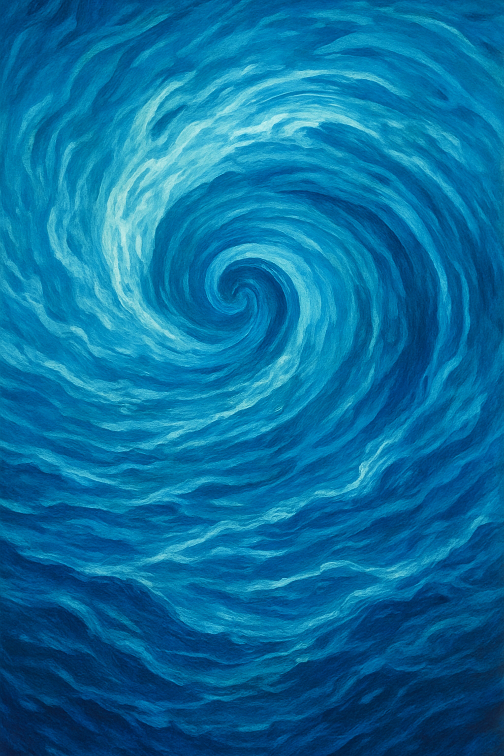
Example4.6.2.Uniform flow past a circular cylinder.
We begin with the complex potential given by \(f(z) = Uz\text{,}\) which corresponds to horizontal uniform flow. We then consider inserting a circular cylinder with boundary \(|z| = a\text{.}\) Clearly, \(f\) satisfies the requirements of the Circle Theorem since it is non-singular for all \(z\text{.}\) Thus, we can construct the following result
Potential flow of consisting of uniform horizontal flow of speed \(U\) at infinity, past a circular cylinder of radius \(a\) (placed at the origin) is given by the complex potential
\begin{equation}
w(z) = \phi + \im \psi = Uz + \overline{\frac{Ua^2}{\overline{z}}} = Uz + \frac{Ua^2}{z}.\tag{4.6.2}
\end{equation}
Previously, it was demonstrated, via (4.6.2) that uniform horizontal flow past a circle (circular cylinder) of radius \(a\) can be found via the complex potential function
\begin{equation}
w(z) = Uz + \frac{Ua^2}{z}, \tag{4.6.3}
\end{equation}
corresponding to uniform horizontal flow at infinity of speed \(U\text{.}\)
Conclude that on the surface of the cylinder, the maximum velocity is \(|\bu| = 2U\text{.}\) Where does this maximum velocity occur? Where do stagnation points in the flow (where the velocity is zero) occur?
From the above, we clearly see that the magnitude is \(|u - \im v| = 2U\sin\theta\) so the maximum speed on the cylinder is \(2U\text{.}\) This value is obtained at the top and bottom with \(\theta = \pm \pi/2\text{.}\) The stagnation point is found where the speed is zero, and this is at the fore and aft points, \(\theta = \pi, 0\text{.}\)
where we have set the constant on the RHS of the formula to be \(p_\infty/\rho\text{,}\) setting a reference pressure. We now only need to substitute the speed on the cylinder, \(|\bu| = U(4\sin^2\theta)\text{,}\) giving
\begin{equation*}
p = p_\infty + \frac{\rho}{2}U^2(1 - 4\sin^2\theta)
\end{equation*}
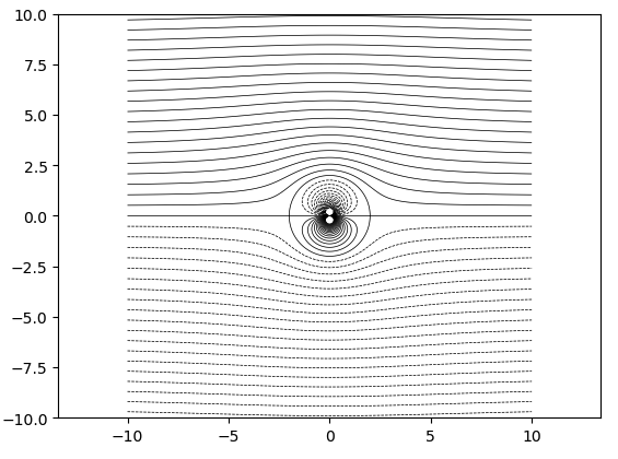
It is possible to add a line vortex to the interior of the circular cylinder, centred at \(z = 0\) by writing in addition to (4.6.3), an additional term:
\begin{equation*}
w(z) = U \left(z + \frac{a^2}{z}\right) - \frac{\im\Gamma}{2\pi} \log z.
\end{equation*}
Verify again that the above modification does not change the streamline properties of \(|z| = a\text{.}\)
The addition of the line vortex does not change the streamline patterns on the cylinder since it is a linear addition. Indeed, on the surface, we have from the addition:
The fact that the stagnation point shifts, moving on the topside or bottomside of the circular cylinder, dependent on the value of \(\Gamma\) will result in an asymmetry in the pressure, causing net force on one side of the cylinder. This is related to the well-known Magnus effect, which is used by athletes to cause a ball’s trajectory to move from a straight path.
The point of the previous exercise is to note that when \(\Gamma \neq 0\text{,}\) this shifts the location of the stagnation point. For example, if \(\Gamma = 4\pi a U\text{,}\) then the stagnation points are found at
\begin{equation}
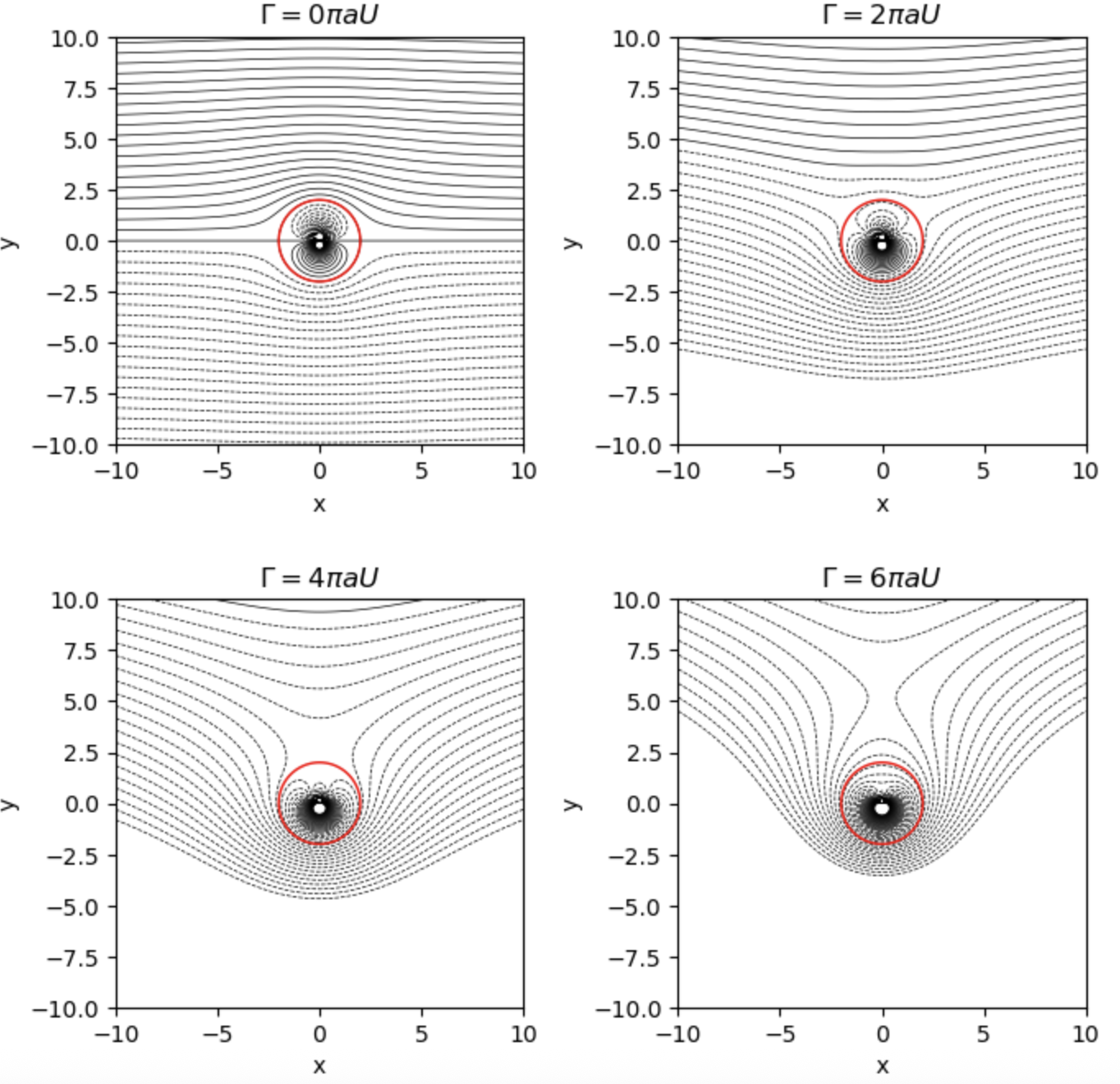
z = G(\zeta) = \zeta + \frac{a^2}{\zeta}\tag{4.6.6}
\end{equation}
where \(a > 0\) is a parameter. The mapping is conformal at all points except \(\zeta = 0\) (pole) and \(\zeta = \pm a\) where \(G'(\zeta) = 0\text{.}\)
Provided that \(r > a\text{,}\) this the equation of an ellipse with principle radii \(r + a^2/r\) and \(r - a^2/r\text{.}\) The orientation of circles is preserved, with an anticlockwise rotation in \(\zeta\) corresponding to anticlockwise in \(z\text{.}\) The exterior of the circle \(|\zeta| = r\) is mapped to the exterior of the ellipse in \(z\text{.}\)
In addition note that if \(r \to a\text{,}\) the ellipses tends to the line segment
\begin{equation*}
S = \{ z = 2a\cos\theta \, | 0 \leq \theta \leq \pi\},
\end{equation*}
which then ranges from \(z = 2a\) for \(\theta = 0\) to \(z = -2a\) for \(\theta = \pi\text{.}\) As \(\theta\) further ranges in \([\pi, 2\pi)\text{,}\) this traverses the horizontal plate again. One can interpret it as traversing the top or the bottom side of the plate (a view strengthened from considering the limiting images). This is shown in Figure 4.6.8.
Figure4.6.8.The Joukowski transformation in (4.6.6) sends circles with radius \(r \geq 1\) to ellipses in the \(z-\)plane. In the limit \(r \to a^+\text{,}\) this approaches a horizontal plate of length \(4a\text{.}\)
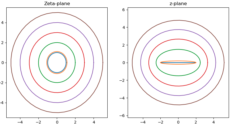
If on the other hand, \(r < a\text{,}\) then we can verify that the mapping still produces ellipses, but now with principal radii \(r + a^2/r\) and \(a^2/r - r\text{.}\) The orientation is now reversed, with anticlockwise orientation in \(\zeta\) mapped to clockwise orientation. Therefore, it is the case that the interior of the discs with \(|\zeta| = r\) are mapped to the exterior of ellipses in \(z\text{.}\) Again, in the limit that \(r \to a^-\) the images approach a flat plate of length \(4a\) on the axis.
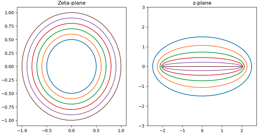
Figure4.6.9.The Joukowski transformation in (4.6.6) sends circles with radius \(r \leq 1\) to ellipses in the \(z-\)plane. As \(r \to \infty\text{,}\) these tend to infinitely large circles. The values here are \(r = 0.5, 0.6, 0.7, 0.8, 0.9, 1.\)
As noted in the exercises of Exercises 1.3, if we let
\begin{equation*}
z + 2a = r_1 \e^{\im \theta_1} \quad \text{and} \quad
z - 2a = r_2 \e^{\im \theta_2},
\end{equation*}
and take \(\theta_1, \theta_2 \in [0, 2\pi)\text{,}\) this corresponds to a single branch cut between \(z = -2a\) and \(z = 2a\text{.}\) This branch cut choice is the most convenient since then it directly coincides with the central axis of the ellipse.
Once the proper branch structure has been chosen, we can define the two possible inverses of the mapping, corresponding to the positive and negative branches. We have
Let us return to the perspective of images from the \(\zeta\)-plane to the \(z\)-plane. We can now consider the images of circles in the \(\zeta\)-plane that have either been horizontally shifted and/or vertically shifted. The two critical points (points where the map is not conformal) mentioned above correspond to either \(\zeta = \pm a\) or \(z = \pm 2a\text{.}\)
Firstly in Figure 4.6.10, we see that horizontal shifts of the circle will corresponding to shifting and deforming the ellipse such that, as a critical point is approached, this forms a point of non-conformality in the image (a cusp).
Figure4.6.10.We now consider shifting the circle with \(|\zeta| = 2\) to the left, so that the circumferance passes through the critical point at \(\zeta = a = 1\text{.}\) This produces an image that resembles an aerofoil with a sharp trailing edge.
Figure4.6.11.Vertical shifts correspond to changing the top-bottom symmetry of the aerofoil. In this case, notice that if the circle in the left plane passes through a critical point, this produces a self-intersecting shape.